


.png)








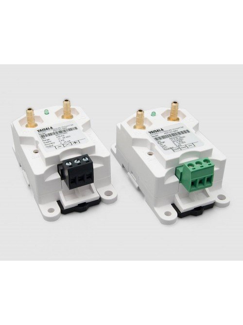
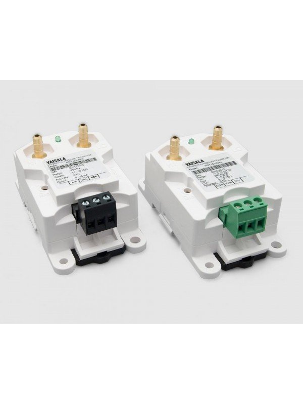
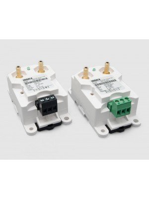
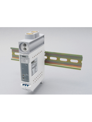
The Vaisala PDT101 and PDT102 provide precise low differential-pressure measurement for cleanrooms, isolation rooms, regulated facilities, data centres and air-handling systems.
The Vaisala PDT101 and PDT102 differential pressure transmitters are designed to measure very small pressure differences between rooms, corridors, airlocks, ducts and air-handling components.
Accurate differential-pressure monitoring helps confirm the intended direction of airflow. This is essential for maintaining cleanroom pressure cascades, protecting isolation areas, preventing contamination migration and identifying blocked filters or abnormal fan performance.
Both transmitters provide analog outputs for connection to building-management systems, programmable controllers, data loggers and environmental monitoring systems. They can also be incorporated into the Vaisala viewLinc Continuous Monitoring System for documented monitoring, alarming and reporting in regulated facilities.
| Selection Requirement | Recommended Model | Reason |
|---|---|---|
| General critical-room monitoring | PDT101 bidirectional | Compact transmitter with ±60 Pa or ±125 Pa ranges and 0.40% span accuracy |
| Highest-accuracy cleanroom monitoring | PDT102 | Accuracy options of 0.25% or 0.50% of span for demanding regulated applications |
| AHU fan or filter monitoring | PDT101 unidirectional | 0–500 Pa range designed for pressure drop across fans and filters |
| In-place calibration without disconnecting tubes | PDT102 with process valve actuator and test jacks | Supports online checking and calibration with minimal disruption |
| Compact wall, panel or DIN-rail mounting | PDT101 | Small, lightweight enclosure with flexible mounting methods |
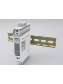
| Ultrathin DIN-rail installation | PDT102 | Narrow 22.6 mm profile conserves cabinet space |
The PDT101 is the flexible choice for critical environments and air-handling systems. Bidirectional models measure positive and negative pressure around zero for room-to-room monitoring, while unidirectional models measure pressure drop across fans, filters and other HVAC components.
| Model Family | Measurement Range | Output | Typical Use |
|---|---|---|---|
| PDT101-P4C | ±60 Pa | 4–20 mA | Critical-room and cleanroom pressure monitoring |
| PDT101-P4V | ±60 Pa | 0–5 V | Critical-room monitoring with voltage input |
| PDT101-P4C2 | ±125 Pa | 4–20 mA | Wider bidirectional room-pressure range |
| PDT101-P4V2 | ±125 Pa | 0–5 V | Wider bidirectional range with voltage output |
| PDT101-P10C | 0–500 Pa | 4–20 mA | AHU fan and filter differential pressure |
| PDT101-P10V | 0–500 Pa | 0–10 V | AHU fan and filter monitoring with voltage output |
Equivalent inch-water-column variants are available. Confirm the required engineering unit, range, output and calibration-certificate requirement when ordering.
| Measurement Specification | Performance |
|---|---|
| Bidirectional Accuracy | 0.40% of span |
| Unidirectional Accuracy | 1% of span |
| Long-Term Stability | ±0.25% of span per year or better |
| Response Time | 250 ms from 10% to 90% |
| Warm-Up Time | 15 seconds |
| Compensated Temperature Range | +2 to +54 °C |
| Proof Pressure | 1.0 bar |
| Burst and Static Pressure | 1.7 bar |
The PDT102 is designed primarily for life-science and high-technology cleanrooms where very high accuracy, sensitivity and repeatability are required. Its micromachined MEMS silicon diaphragm provides stable ultra-low-pressure measurement.
| Measurement Specification | Performance |
|---|---|
| Bidirectional Range | ±50 Pa or ±0.25 inH₂O |
| Accuracy Options | 0.25% or 0.50% of span |
| Repeatability | 0.03% for 0.25%-accuracy model; 0.05% for 0.50%-accuracy model |
| Electrical Resolution | 1 × 10⁻⁴ of span |
| Long-Term Stability | ±0.25% of span per year or better |
| Response Time | 250 ms from 10% to 90% |
| Warm-Up Time | 15 seconds |
| Compensated Temperature Range | +2 to +57 °C |
| Proof Pressure | 0.7 bar |
| Burst and Static Pressure | 1.7 bar |
| Output | Wiring | Recommended Use |
|---|---|---|
| 4–20 mA | Two-wire loop powered | Long cable runs, industrial controllers, data loggers and monitoring cabinets |
| 0–5 V | Three-wire | Controllers and acquisition systems with compatible voltage inputs |
| 0–10 V | Three-wire; PDT101 unidirectional models | Building-management and HVAC controllers using 0–10 V inputs |
| Specification | PDT101 | PDT102 |
|---|---|---|
| Operating Voltage | 12–36 V DC for 4–20 mA; voltage versions also support specified DC or 24 V AC supplies | 12–36 V DC |
| Process Connection | ¼-inch barbed brass fittings | ⅛-inch NPT female |
| Measured Medium | Clean, dry air and non-conducting, non-corrosive gases | Clean, dry air and non-conducting, non-corrosive gases |
| Mounting | Wall or EN 50022 DIN rail | EN 50022, EN 50035 or EN 50045 DIN rail |
| Protection Rating | IP40 | IP30 |
| Operating Temperature | −18 to +70 °C | −29 to +70 °C |
| Storage Temperature | −40 to +82 °C | −40 to +82 °C |
| Approximate Weight | 0.07 kg | 0.16 kg |
A cleanroom pressure cascade uses controlled pressure differences to establish the required airflow direction between adjoining spaces. A transmitter is typically connected across a wall, door or room boundary, with the high- and low-pressure tubes routed to representative pressure locations.
| Monitoring Point | Purpose |
|---|---|
| Cleanroom to Corridor | Confirms positive pressure that helps keep unfiltered corridor air outside the cleanroom |
| Airlock to Adjacent Room | Verifies the designed step in a multi-room pressure cascade |
| Negative Isolation Room | Confirms inward airflow to help contain hazardous or infectious material |
| Positive Protective Room | Confirms outward airflow to protect sensitive products or occupants |
| Filter or Fan | Measures pressure drop for condition and performance monitoring |
PDT101 and PDT102 analog signals can be integrated with the Vaisala viewLinc Continuous Monitoring System through a compatible input device or the Vaisala CAB100 Industrial Cabinet.
The Vaisala CAB100 Industrial Cabinet provides a centralised and organised method of connecting differential-pressure measurements to viewLinc. It can contain selected pressure transmitters, analog-input channels, power components and communication interfaces in a preconfigured enclosure.
This arrangement is particularly useful in pharmaceutical plants, biotechnology facilities, laboratories and semiconductor cleanrooms where several room-pressure measurements must be installed, powered, commissioned and maintained as one monitoring system.
| System Component | Function |
|---|---|
| PDT101 or PDT102 | Measures the differential pressure between the high- and low-pressure locations |
| 4–20 mA or Voltage Signal | Transfers the scaled differential-pressure measurement to a compatible CAB100 input configuration |
| CAB100 Cabinet | Centralises selected transmitters, analog inputs, power equipment, communication devices and field wiring |
| viewLinc Enterprise Server | Stores measurement records and provides displays, threshold alarms, reports and audit-trail functions |
| Project Requirement | Recommended CAB100 Approach |
|---|---|
| Centralised PDT101 installation | Select a CAB100 PDT101 configuration according to the required number of pressure channels and cabinet capacity |
| Remote PDT101 or PDT102 transmitter | Use a compatible CAB100 analog-input configuration after confirming signal type, scaling and power requirements |
| Pressure plus other analog measurements | Select a CAB100 analog-input or suitable mixed configuration reviewed against the complete channel requirement |
| Higher channel quantity | Use the larger CAB100B or multiple cabinets according to the system architecture |
| Regulated cleanroom project | Define pressure ranges, engineering units, alarm thresholds, calibration requirements and viewLinc validation documentation before configuration |
View the Vaisala CAB100 Industrial Cabinet
Seacom Process Instruments supplies and supports the Vaisala PDT101 and PDT102 differential pressure transmitters in Malaysia for cleanrooms, isolation rooms, pharmaceutical facilities, laboratories, semiconductor production, data centres and air-handling systems.
Our team can assist with model selection, pressure range, output type, tubing arrangement, mounting, CAB100 cabinet configuration, viewLinc integration, commissioning, calibration and GxP documentation.
Download |

.
The Vaisala PTU300 combined barometric pressure, relative humidity and temperature in one transmitter. The series is discontinued and has been replaced by a suitable Indigo520 barometric-pressure configuration with an application-specific HMP probe.
The Vaisala DPT145 provides online dew-point, pressure and temperature measurement for SF6-insulated electrical equipment. The model is being discontinued and should not be specified for new projects.
The Vaisala PTB330 provides accurate, stable barometric-pressure measurement for professional meteorology, aviation, maritime systems, laboratories and demanding environmental applications.
The Vaisala DPT146 combines dew-point and process-pressure measurement in one compact transmitter for compressed-air systems. This model is discontinued and should not be selected for new projects.

The Dickson PR125, PR325 and PR525 are rugged battery-powered pressure data loggers for recording equipment and line pressure without a permanently connected computer.
The Dickson PW4 and PW8 provide a continuous paper record of pressure at the measurement point for equipment monitoring, testing, troubleshooting and permanent visual documentation.
The Vaisala PDT101 and PDT102 provide precise low differential-pressure measurement for cleanrooms, isolation rooms, regulated facilities, data centres and air-handling systems.
 PDT101 catalogue
(698.65k)
PDT101 catalogue
(698.65k)