- Out-of-Stock
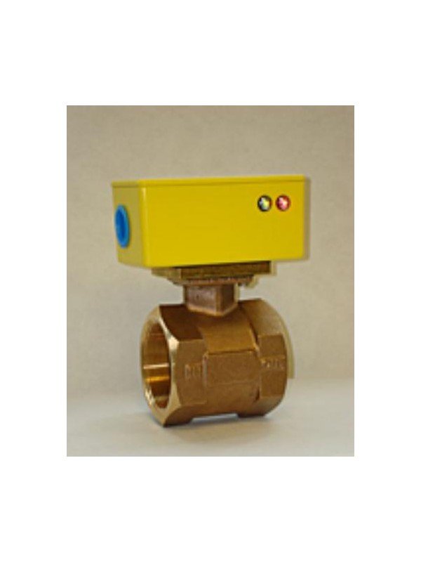



The RCM Flo-Gard II is a robust in-line liquid flow switch for detecting high or low flow conditions in cooling, lubrication, pump-protection and process-control applications.
The RCM Flo-Gard II liquid flow switch is designed to detect high or low liquid-flow conditions in industrial piping systems. Its robust in-line metal construction is suitable for safety interlocks, equipment protection, alarm circuits and automatic process control.
One or two independently adjustable SPDT reed switches detect the position of a magnet permanently connected to the internal bellows mechanism. When the liquid flow reaches the selected switching point, the reed switch changes contact state to operate an alarm, relay, pump-control circuit or compatible controller input.

| Specification | Performance |
|---|---|
| Manufacturer | RCM Industries |
| Model | Flo-Gard II |
| Service | Compatible liquids |
| Installation | Fixed, in-line mounting |
| Switch type | One or two independently adjustable SPDT reed switches |
| Body materials | Brass or 316 stainless steel, according to model |
| Pipe sizes | ½ to 8 inches |
| Complete liquid-flow range | Approximately 4 GPH to 3,000 GPM, depending on size and configuration |
| Setability | Approximately ±5% of full scale |
| Hysteresis | Approximately ±13% of full scale |
| Maximum liquid temperature | Up to 100 °C for applicable standard configurations |
| Maximum pressure | Up to approximately 28 bar for applicable configurations |
| Enclosure | NEMA 4X / IP66 for applicable models |
| Ambient temperature | Up to approximately 50 °C |
| Options | Low-flow range, alternative seals, LED indication and intrinsically safe approval |
Maximum pressure, temperature, switching range and material compatibility depend on the selected model, body size, seals and options. Confirm the complete operating conditions before ordering.
Liquid flowing through the body produces a force on the internal sensing mechanism. Movement of the bellows changes the position of a permanent magnet. The magnet operates an externally isolated reed switch when the flow reaches the selected set point.
Because the electrical switch is magnetically actuated, the switching components remain isolated from the process liquid. This arrangement provides reliable flow detection without requiring the reed switch itself to contact the measured liquid.
| Configuration | Function | Typical use |
|---|---|---|
| One SPDT switch | Provides one independently adjustable switching point | Low-flow alarm, high-flow alarm, pump protection or equipment interlock |
| Two SPDT switches | Provides two independently adjustable switching points | Separate warning and shutdown points or independent high-flow and low-flow alarms |
The switching direction and contact selection should be chosen so the controlled equipment moves to a safe condition if flow is lost, power is interrupted or wiring is damaged.
Standard Flo-Gard II models are intended for general industrial locations. Intrinsically safe versions are available for selected hazardous-location applications when used with the appropriate approved electrical circuit and associated apparatus.
| Version | Description |
|---|---|
| General purpose | Standard industrial flow-switch configuration for non-hazardous locations |
| Option IS | Intrinsically safe version for approved hazardous-location installations |
| Option LED | Local LED indication to show switch status and simplify field adjustment |
| Option IS with LED | Hazardous-location configuration with local visual switch indication |
Hazardous-area installation: confirm the complete model approval, entity parameters, barrier or isolator, cable arrangement, area classification and local regulatory requirements before installation.
| Specification | General-purpose version |
|---|---|
| Contact arrangement | SPDT reed switch |
| Contact rating | 10 W maximum |
| Maximum DC voltage | 175 VDC |
| Maximum AC voltage | 125 VAC |
| Maximum switching current | 350 mA |
Do not exceed any individual voltage, current or power limit. Inductive loads such as contactors, solenoid valves and relays may require a suitable suppression device or an interposing relay to protect the reed-switch contacts.
| Parameter | Option IS / LED |
|---|---|
| Maximum voltage | Vmax = 28 V |
| Maximum current | Imax = 110 mA |
| Maximum power | Pmax = 1.2 W |
| Internal capacitance | Ci = 0 µF |
| Internal inductance | Li = 0 µH |
| CSA / NRTL classification | Class I, Division 1, Groups A, B, C and D; Class II, Division 1, Groups E, F and G |
| ATEX classification | Ex ia IIC, Zone 0, II 1G T4 for applicable approved configurations |
Always verify these parameters against the certificate supplied with the ordered unit. Product approvals and allowable ambient conditions can vary according to model revision and configuration.
Select the Flo-Gard II according to the actual switching requirement rather than pipe size alone. The chosen full-scale flow range should allow the required alarm or control point to fall within the adjustable portion of the scale.
Provide the following information when requesting a quotation:
Check the chemical compatibility of the liquid with the body, bellows, seals and all other wetted components. Brass construction is suitable for many water and general-service applications, while 316 stainless steel may be preferred for corrosive liquids or processes requiring stainless-steel wetted parts.
Optional sealing materials may include Viton, EPR or PTFE according to configuration. Selection must consider the liquid composition, concentration, temperature and cleaning chemicals.
Seacom Process Instruments supplies and supports the RCM Flo-Gard II liquid flow switch. Our team can assist with flow-range selection, process connections, body and seal materials, switch configuration, hazardous-area options and electrical requirements.
Contact Seacom with the liquid, pipe size, operating flow, required set point, pressure, temperature, material requirements and area classification so we can recommend a suitable Flo-Gard II configuration.
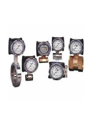
The RCM Flo-Gage Series 7000 and 8000 are rugged direct-reading differential-pressure flow meters for water, oils, chemicals, compressed air and other compatible liquids or gases.
The RCM Flo-Gage Series 7000 and 8000 are rugged direct-reading differential-pressure flow meters for water, oils, chemicals, compressed air and other compatible liquids or gases.