- Out-of-Stock
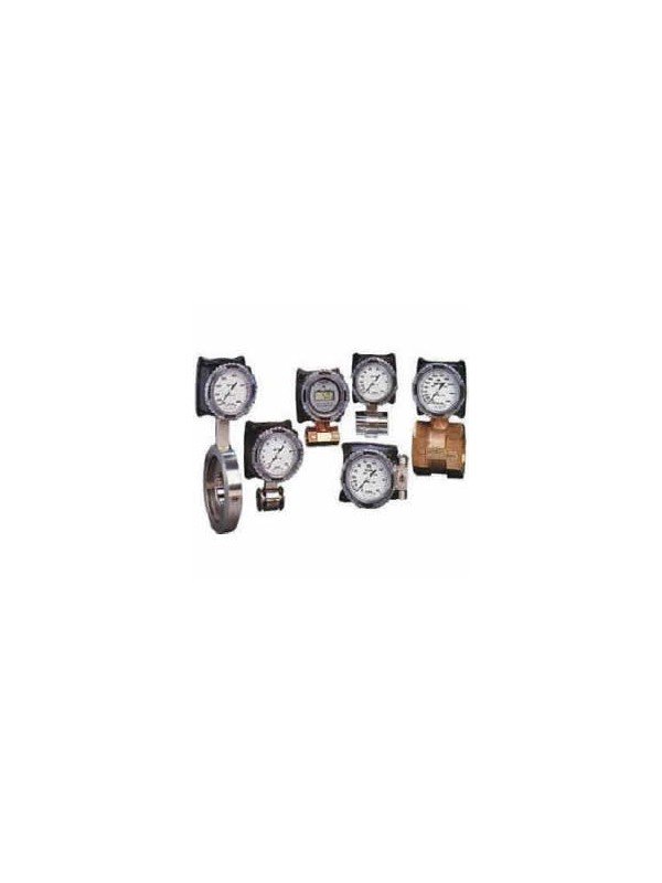
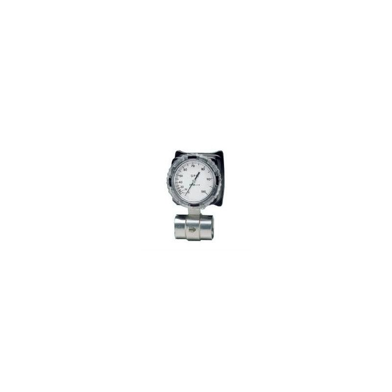
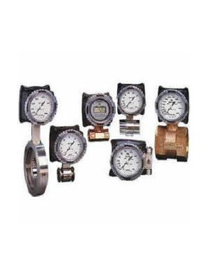
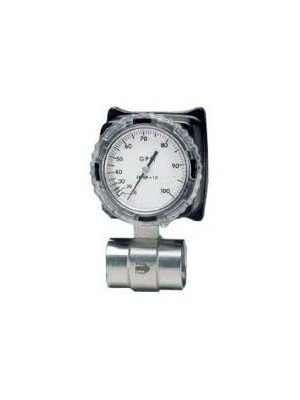



The RCM Flo-Gage Series 7000 and 8000 are rugged direct-reading differential-pressure flow meters for water, oils, chemicals, compressed air and other compatible liquids or gases.
The RCM Flo-Gage is a direct-reading differential-pressure flow meter for industrial liquid and gas applications. A built-in calibrated nozzle creates a pressure differential related to the flow rate, while the large analogue dial displays the measurement directly in engineering units such as GPM, L/min, SCFM or Nm³/h.
The Flo-Gage is self-contained and does not require separate orifice plates, impulse tubing, equalising valves or an external differential-pressure indicator. Its robust in-line metal construction is suitable for applications where durability, simple operation and clear local indication are important.
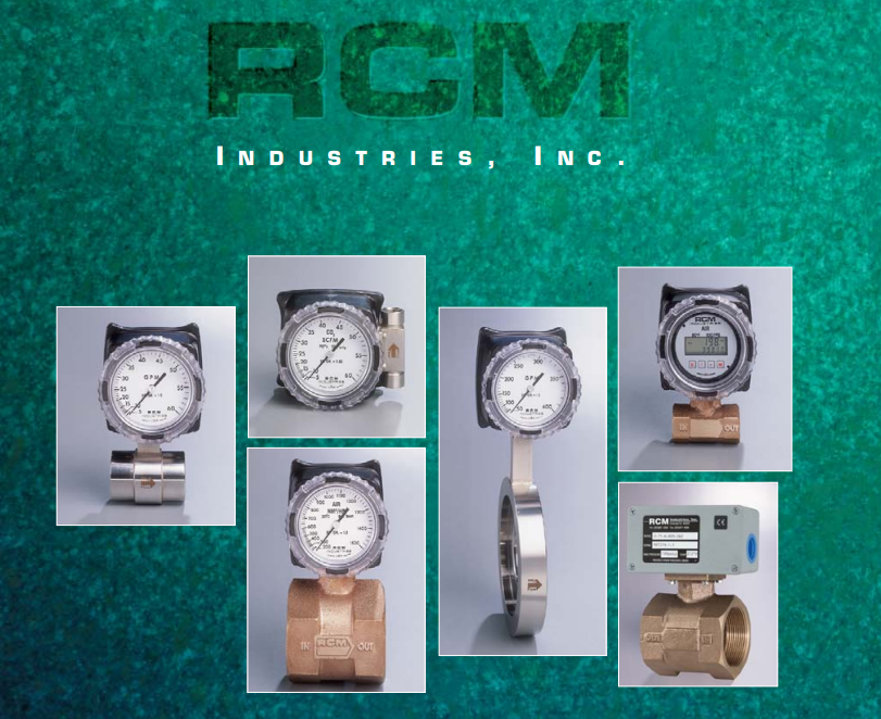
The Flo-Gage operates using the differential-pressure principle. As fluid passes through the meter’s calibrated nozzle, it creates a pressure difference between the upstream and downstream sensing points. This differential pressure moves the internal bellows mechanism and positions the pointer on the calibrated flow scale.
The pressure difference is proportional to the square of the flow rate. The dial is factory calibrated so the operator reads flow directly without performing a differential-pressure calculation.
Integrated differential-pressure meter: although the Flo-Gage uses a principle similar to an orifice flowmeter, the calibrated nozzle, pressure sensing, mechanical indicator and scale are integrated into one complete in-line instrument.
| Series | Connection | Nominal sizes | Typical use |
|---|---|---|---|
| Series 7000 | NPT or BSP threaded connection | ¼ to 3 inches | Small and medium industrial pipelines |
| Series 8000 | Wafer-style installation between flanges | ½ to 8 inches | Medium and large pipelines requiring a compact flanged installation |
| Specification | Standard | Optional or configuration dependent |
|---|---|---|
| Measurement principle | Integrated differential-pressure nozzle | |
| Display | 90 mm direct-reading analogue dial | |
| Scale | Approximately 270 degrees | |
| Measuring range | Approximately 6:1 | |
| Accuracy | ±3% of full scale | |
| Repeatability | Approximately ±1% of full scale | |
| Maximum pressure | Approximately 180 psig or 12.4 bar | Up to approximately 400 psig or 27.6 bar |
| Minimum operating pressure | Approximately 10 psig or 0.7 bar | |
| Maximum temperature | Up to approximately 100 °C | Up to approximately 177 °C |
| Minimum temperature | Approximately −34 °C; protect liquids from freezing | |
| Body materials | Bronze, 316 stainless steel or Monel according to configuration | |
| External power | Not required for local mechanical indication | Required for electrical transmitters and powered accessories |
Pressure and temperature limits depend on the body material, seals, process connection and selected options. Confirm the complete model specification for the intended application.
The liquid Flo-Gage is suitable for water and many low- or medium-viscosity liquids that do not deposit solids inside the measuring passage and are compatible with the selected wetted materials.
Standard liquid configurations can accommodate viscosities up to approximately 500 cP, subject to application review and calibration. Provide the liquid name, specific gravity and viscosity when requesting a quotation.
Gas-calibrated Flo-Gage models are available for compressed air, nitrogen, oxygen, carbon dioxide and other compatible non-toxic industrial gases. Gas scales are normally specified in SCFM or Nm³/h for defined reference conditions.
Selected configurations are available for saturated or superheated steam. Steam service requires the appropriate high-temperature construction, seals, pressure rating, scale and installation arrangement.
Gas sizing: provide the gas composition, normal and maximum pressure, operating temperature, required flow range and preferred reference conditions. A gas scale calibrated for one pressure or gas cannot automatically be used under different operating conditions.
| Service | Approximate complete range | Available sizes |
|---|---|---|
| Liquid | 4 GPH to 3,000 GPM | ¼ to 8 inches, depending on series and range |
| Liquid metric | 15 L/h to approximately 12,000 L/min | Depending on series and selected scale |
| Gas | 40 SCFH to 20,000 SCFM | Depending on size, gas and calibration conditions |
| Optional low flow | Selected ranges below 2 GPM | Normally ½-inch configuration with Option ES |
The complete catalogue contains the available full-scale ranges for each pipe size. Select a scale that places the normal operating flow within the upper half of the dial whenever possible.
The Flo-Gage can be fitted with one or two independently adjustable SPDT reed switches. These switches can provide high-flow or low-flow signalling for alarms, pump protection, equipment interlocks and control circuits.
| Option | Function | Typical application |
|---|---|---|
| 1S2 | One adjustable SPDT reed switch | Single high-flow or low-flow alarm |
| 2S2 | Two independently adjustable SPDT reed switches | Separate warning and shutdown points |
| IS versions | Intrinsically safe switch configuration | Approved hazardous-location installations |
| LED versions | Local LED switch-status indication | Convenient viewing and field adjustment |

The example above shows a Flo-Gage with reed switches integrated into a chiller system to detect a low cooling-water flow condition.
Electrical transmitter options allow the indicated flow to be sent to a PLC, DCS, recorder, remote display or building-management system. Available configurations depend on the model, application and required output.
| Output | Purpose |
|---|---|
| 4–20 mA | Continuous analogue flow signal for remote indication, recording or control |
| Frequency output | Flow-related pulse or frequency signal for compatible receiving equipment |
| High/low contacts | Alarm or control contacts for selected transmitter configurations |
| Digital display options | Local digital indication with additional communication choices according to model |
Confirm the power supply, output type, electrical load, receiving-device input and hazardous-area requirements before ordering.
Select the Flo-Gage according to the actual process conditions, required flow range and output—not pipe size alone. A correctly selected scale improves readability and keeps normal operation within the preferred portion of the measuring range.
Provide the following information when requesting a quotation:
The minimum readable flow is normally approximately 15% of full scale. For clearer reading and improved practical performance, select a meter that places normal operation within the upper half of the scale.
Do not select an unnecessarily high full-scale range. An oversized range compresses the normal operating point into the lower part of the dial and makes small flow changes more difficult to observe.
Seacom Process Instruments supplies and supports RCM Flo-Gage Series 7000 and 8000 flow meters for liquid, gas and selected steam applications. Our team can assist with flow-range selection, process connections, materials, calibration units, alarm switches and transmitter outputs.
Contact Seacom with the process medium, flow range, pressure, temperature, pipe size and output requirements so we can recommend the appropriate Flo-Gage configuration.
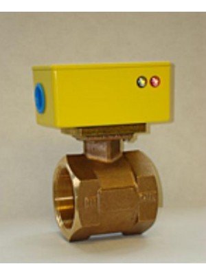
The RCM Flo-Gard II is a robust in-line liquid flow switch for detecting high or low flow conditions in cooling, lubrication, pump-protection and process-control applications.
The RCM Flo-Gard II is a robust in-line liquid flow switch for detecting high or low flow conditions in cooling, lubrication, pump-protection and process-control applications.